How to design an EMC surge protection circuit, from principle to selection
2024-03-27 16:06:21 14
A surge protection circuit is a type of circuit known as an AC grid line voltage peak protector. However, there are no special restrictions in AC power lines. A surge protector or surge protection device is a device that provides surge suppression or suppression of voltage spikes so sensitive equipment does not get damaged.
Surge protectors can handle voltage spikes in the range of up to several thousand volts (depending on the type of surge protector). There are also surge suppressors that can only handle a few hundred volts, and so on. Although surge protectors are designed to withstand high voltage spikes for short periods of time, they are not designed to withstand longer durations.
What is a power surge?
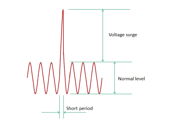
Typically, a surge is a sudden increase in level or amplitude from a normal or standard value. In electricity, surge is commonly used to describe voltage transients, voltage surges, or voltage spikes. Voltage surges, spikes or transients are not permanent events. It only occurs for a short period of time, but without countermeasures it is enough to damage the device.
Voltage surges occur not only in power lines, but also in circuits with inductive properties. However, voltage surges in power lines are the most damaging because they can be in the multi-kilovolt range.
The image below shows a surge on an AC power line.
 AC line transient surge protectors are commonly installed in homes, offices, and buildings to prevent damage to equipment or installations. It should be installed where its source code is available on all devices or devices. This way, all equipment will be protected from line surges and spikes. This method is called universal surge protection. If all appliances or appliances have local surge protection circuitry, a universal surge protector may not be needed.
Two Main Categories of Surge Protection Circuits Used in Power Lines
1. Main surge protector
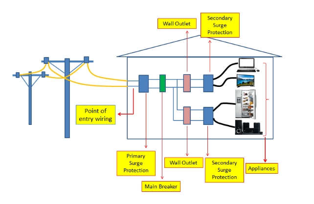
Primary surge protection devices are installed at the electrical wiring entrance to a house, office or building. It will protect any equipment or appliances connected to the line after the entry point. Typically, primary surge protectors are very powerful. However, it is large, bulky, and expensive.
2. Secondary surge protector
Secondary surge protectors are not as effective and powerful as primary surge protectors.
However, it is portable and easy to use. Typically, this surge protector plugs easily into an electrical outlet. It only provides protection for devices that draw power from an electrical outlet that has a secondary surge protector installed.
The diagram below shows how primary and secondary surge protectors are installed in a building.
Common Types of Secondary Surge Protection Circuits
There are few known secondary surge protection circuits. One is the so-called switchboard. The power strip easily plugs into an electrical outlet. In addition to this, it comes with multiple power outlets into which multiple devices and appliances can be plugged in and is protected from surges. The most important function of a power strip is the ability to terminate power in the event of a power surge.
Another known type of secondary surge protector is the well-known UPS or uninterruptible power supply. Some sophisticated UPS have built-in surge protectors that provide the same safety protection features as a power strip.
How does a surge protector work?
There is a surge protector
In the event of a power surge, the power can be cut off. This type of surge protector is complicated, complicated, and of course expensive. The basic components of this type are the voltage sensor, controller and latch/unlock circuit. The voltage sensor will monitor the line voltage and the controller will read the sensed voltage and decide when to signal the termination voltage to the latch/unlock circuit. A latch/unlock circuit is a controllable power contactor or power switch that connects or disconnects line voltage.
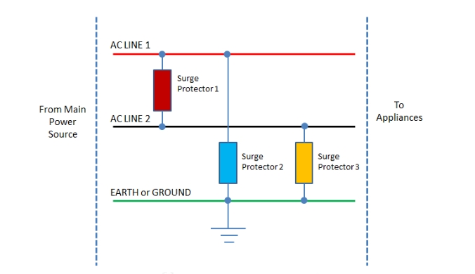
There is also a type of surge protector that does not provide voltage shutdown but simply clamps voltage transients and absorbs energy. This type of surge protector is often used as a built-in surge protector, for example in switch mode power supplies. This type of protection is effective down to several thousand volts. This surge protection is best described in a circuit as shown in the diagram below.
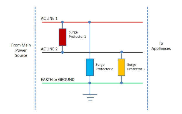
Surge protector 1 on ACLINE 1 and AC2 is called differential mode surge suppression. Surge protectors 2 and 3 are both called common mode surge suppression. Differential mode surge suppressors clamp any voltage spikes on ACLINE1 and ACLINE2. It is called differential mode because it is installed on two hot wires. Common mode, on the other hand, is the term used for surge protectors 2 and 3 because both clamp voltage transients on a single hot wire relative to ground. In less stringent surge requirements, surge protector 1 is sufficient to pass the standard. However, for very stringent requirements such as higher surge voltages, surge protectors 2 and 3 are added.
Causes of voltage surges
Voltage surges occur for many reasons. This can be caused by lightning, power system switching (such as capacitor banks), resonant circuits with switching equipment, wiring errors, and sudden opening and closing of switches, motors, and other highly inductive appliances and equipment. AC line voltage surges occur anywhere in the world. Therefore, it is recommended to protect devices and equipment from this damaging event.
Some common surge media
These are common paths through which a surge or voltage spike can enter the device or equipment that uses it.
Power Cords – This is the number one medium for electrical surges since all electrical and electronic equipment uses AC power. AC line surges are common around the world.
RF line – includes antenna. Antennas are susceptible to lightning strikes. Lightning can produce very high voltage spikes for a short period of time. When lightning strikes the antenna, it will penetrate the RF receiver.
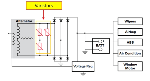
Automotive Alternator – In automotive electronics, voltage surges are also defined. This is because the alternator is capable of generating high voltage spikes during load dumps.
Inductive Circuits/Loads – Any inductive circuit or load will always introduce surge voltages. Typically, this surge is called induced kickback.
Surge standards defined by IEC
IEC61000-4-5 defines the standard for AC power line surges. The table below provides specific descriptions of the categories and voltage levels.

According to the standard, the maximum transient voltage that equipment should withstand and pass is 4kV at Class 4 (despite Class 5, it is still called Class 4).
The transient voltage defined by IEC61000-4-5 is shown in the figure below. It has a rise time of 1.2us, while the pulse width is 50us.
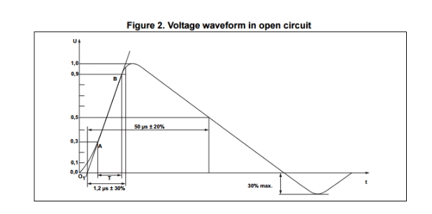
IEC61000-4-5 also defines the short-circuit current shape, as shown in the figure below. It has an 8us rising edge and a 20us pulse width.

The table below shows the corresponding surge or short-circuit current levels for each category. The worst value is 2000A.

What is the short-circuit current specified in IEC61000-4-5?
To answer this question, let me first say that all devices connected to the power cord must have surge protection. Surge protection works by clamping transient voltages to a safer level. Once the surge protection circuit clamps, a short circuit path will occur from the power source to the protective device to power ground.

How to Design a Surge Protection Circuit
Designing surge protection is not difficult. In fact, some electronic devices only have built-in surge protection for one device. This can be a MOV or metal oxide varistor or a transient voltage suppressor TVS. In the picture below, surge protectors 1 to 3 can be MOV or TVS.
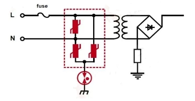 Sometimes surge protection equipment between AC lines is sufficient to pass IEC standards. In rare cases, it is necessary to connect a surge protection circuit between the line and ground. Especially with higher surge voltage requirements (4kV and above).
Using MOV as surge protection device
basic properties
MOV stands for Metal Oxide Varistor; a surge protector commonly used in power lines.
MOV is a voltage dependent resistor
MOV operates like a diode, with non-linear and non-ohmic current and voltage characteristics, but bidirectionally.
Its operation can also be compared to a bidirectional transient voltage suppressor TVS.
When the clamping voltage is not reached, it opens
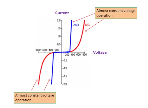
Below is the voltage-current curve of the MOV. As you can see, it has an almost constant voltage on quadrants 1 and 3, making it a bidirectional device. ZnO and SiC represent zinc oxide and silicon carbide respectively. These are two common materials MOVs are made of.
Model selection
Typical MOV voltage ratings are 300Vrms for common 90-264Vac lines. 300Vrms is the RMS or continuously applied voltage that the MOV can withstand. This is not the clamping voltage yet. For example, according to the datasheet, we will use leiditech's 14D471KJ, which has an AC voltage rating of 300Vac but has a clamping voltage of 775V at 50A peak current.
The next thing to verify is that the MOV's surge current rating is capable of handling the levels specified in Table 2 above (considering the maximum level). According to the selected MOV datasheet below, at 2000A and 20us pulse duration, the MOV is capable of handling more than 15 hits but less than 100 hits. 2000A is estimated with a dotted line on the equipment diagram.
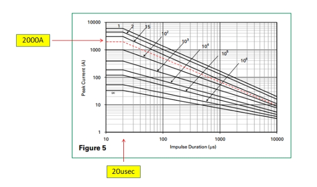
Although the clamping voltage is specified in the datasheet, it may no longer be valid at 2000A. The graph below shows the corresponding clamping voltage at 2000A using the selected MOV. The intersection of the yellow lines is the clamping voltage. Please note that it is already over 1000V. Make sure that all equipment used in the device can withstand this voltage level. Otherwise, consider another MOV with a lower clamping voltage.

MOV ideal location for power line surge protection
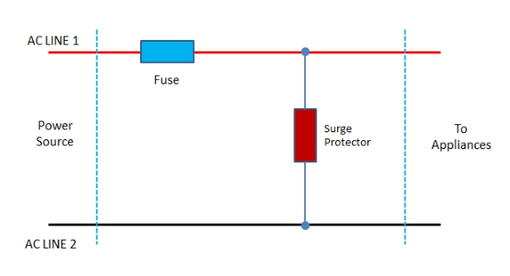
As shown in the picture below, the MOV must be used as a surge protection device and installed close to the fuse. With this wiring, once the surge current is too large for the MOV to handle, the fuse will trip and break the circuit and avoid a possible catastrophic failure.
Surge suppression in automobiles
As mentioned above, surges don't just happen on AC power lines. Voltage surges are also common in automotive systems. Automotive systems use only lead-acid batteries, and the typical full charge voltage is about 12.9V for 6 cells in series, 2.15V per cell. In calculations, a maximum battery voltage of 14V is usually used. This level is not destructive and devices rated at 30V are sufficient for long-term survival. However, this feeling is only true in steady state, not during so-called "load shedding". Load dump is a term used to describe the time when the battery is suddenly disconnected while the generator is charging. For a 12V system, if load dump is not taken into account, voltage spikes of up to 120V can result and are enough to damage equipment.
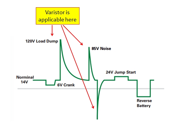
To counteract this load dump condition, surge protection circuits such as TVS and varistors are often used.
In automobiles, the load shedding waveform is defined by ISO7637, as shown below. The maximum peak voltage is 125V. The rise and pulse width duration (T1 and T) are longer compared to the standard defined by IEC61000-4-5.

Ideal Location for Automotive Surge Suppressors
