Lithium and lithium-ion batteries: Clarifying conceptual differences
2024-04-23 15:01:26 27
The lithium battery protection circuit is a key component to ensure the safe and efficient work of the lithium ion battery during use, and its main purpose is to prevent the battery from being damaged under abnormal conditions such as overcharge, over-discharge, over-current, short circuit, etc., to extend the battery life and reduce the safety hazards such as fire and explosion.
1. Introduction to lithium-ion batteries
A lithium-ion battery is a type of secondary battery (rechargeable battery) that primarily relies on lithium ions moving between the positive and negative electrodes to work. In the process of charging and discharging, Li+ is embedded and deembedded between the two electrodes. When charging, Li+ is deembedded from the positive electrode and embedded into the negative electrode through the electrolyte, and the negative electrode is in a lithium-rich state. The opposite is true for electrical discharge.
Lithium-ion battery voltage range 2.8V~4.2V, typical voltage 3.7V, lower than 2.8V or higher than 4.2V, the battery will have the risk of damage.
2, 1C and 0.1C concepts
1C and 0.1C represent that the battery is charged and discharged with 1 and 0.1 times the current of its own capacity, respectively, reflecting the relationship between the current intensity of the battery and the capacity of the battery. A higher C value corresponds to a faster charge and discharge rate, while a lower C value corresponds to a slower and gentler charge and discharge process. In practical applications, choosing the right charge and discharge ratio takes into account factors such as the battery type, the requirements of the battery management system (BMS), the power requirements of the device, and the impact on battery life and safety.
3. Advantages and disadvantages of lithium-ion batteries
The main advantages of lithium-ion batteries:
-
Lithium-ion batteries have high voltage and high energy density;
-
Long cycle life, generally can cycle 500, or even more than 1000 times;
-
The self-discharge rate of Li-ion fully charged at room temperature is about 10% after storage for 1 month.
-
Fast charging, 1C charging capacity can reach 80% of the nominal;
-
The operating temperature range is wide, generally -25~45°C, and it is expected to break through -40-70°C.
-
There is no memory effect like Ni-Cd and Ni-Mh, and the remaining power does not have to be used up before charging;
-
Compared with Ni-Cd and Ni-Mh, it is environmentally friendly and pollution-free (no cadmium, mercury and other heavy metals);
The main disadvantages of lithium-ion batteries:
-
High cost;
-
Need to protect the circuit board, including overcharge and overdischarge protection;
-
Can not be large current discharge, the general discharge current is below 0.5C, too large current leads to internal heat of the battery;
-
Poor safety, easy to explode, fire.
4, the difference between lithium batteries and lithium-ion batteries
Lithium battery and lithium-ion battery are two different concepts, the main differences are as follows:
-
The positive electrode material of lithium battery is manganese dioxide or thionyl chloride, and the negative electrode is lithium;
-
Lithium-ion battery is a lithium battery containing lithium compounds as a positive electrode, in the charge and discharge process, no metal lithium exists, only lithium ions;
-
Lithium battery is also known as a lithium battery, can be continuous discharge, can also be intermittent discharge, once the power is exhausted can not be used again, can not be charged;
-
Lithium-ion batteries, also known as secondary lithium batteries, can be charged and discharged;
5, lithium-ion battery charging mode
The ideal charging mode for lithium-ion batteries is called CCCV mode, that is, constant current and constant voltage mode.
In the following figure, gray is the battery voltage, green is the charging current, and red is the battery capacity.
When the battery voltage is low, the battery is charged with a fixed constant current. When the battery voltage reaches 4.2V, the constant current mode will be switched to the constant voltage mode. Because the battery voltage is not allowed to exceed 4.2V, the system will gradually reduce the charging current until it is close to 0. When the battery voltage is 4.2V and the charging current is 0, the battery is fully charged.

Lithium ion battery CCCV mode
In order to ensure the absolute safety of the battery, the actual charging mode will be more refined, and charging according to constant current for uncertain batteries will cause greater damage to the battery.
-
Test mode, when the battery voltage is lower than 2V, it will wake up the battery with a small current;
-
Trickle charging, also known as precharge mode, when the battery voltage is between 2V and 3V, it will be precharged with 1/10 or 1/20 of the constant current charging;
-
Constant current charging: When the battery voltage rises to more than 3V, the battery will be quickly charged in constant current mode;
-
Constant voltage charging: When the battery voltage reaches 4.2V, the battery will be charged in constant voltage mode;
Like TI's scheme, when the battery voltage is 4.2V and the charging current is low but not 0, about 1/10 of the constant current charging current, the charging will stop, and the battery voltage will be reduced to 4.16V or 4.17V.

The three stages of charging a lithium-ion battery
6, why lithium-ion battery charging cut-off voltage is 4.2V
The following is the relationship between the cycle life of the battery and the charge cut-off voltage, in the initial cycle of the battery, charging to a slightly higher voltage will get a higher single-cycle charge, but only for a short period of time. When the charging voltage of the battery is 50mV or 100mV higher than the recommended maximum voltage of 4.2V, the aging speed of the battery will be greatly accelerated due to slightly overcharging each cycle.
In summary, the charging cut-off voltage of the battery is higher than 4.2V, the higher the voltage, the shorter the cycle life, and the faster the battery capacity decline.
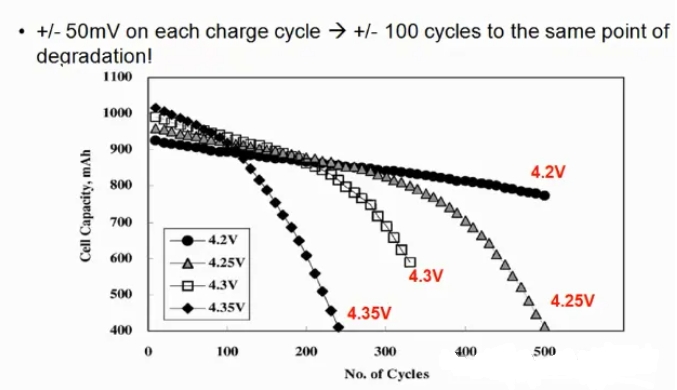
Relationship between cycle life and charge cut-off voltage of Li-ion batteries
7, lithium ion battery discharge curve
The following is the discharge curve of the lithium-ion battery at different discharge currents, it can be seen that the greater the discharge current, the faster the capacity of the battery decreases, the lower the capacity, and the more insufficient the nominal capacity of the battery is used.
When the battery capacity is lower, the internal resistance of the battery will increase more, and when the current is discharged, the internal resistance will grow faster.
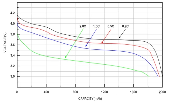
Discharge curve of lithium ion battery at different discharge current
It can be seen from the battery discharge curve at different temperatures that the lower the temperature, the faster the battery capacity decreases and the more inadequate the discharge.
The temperature of the battery is below 0 degrees, the internal active ingredients are very weak, and the internal resistance will correspondingly increase; Excessive temperatures can also damage batteries.
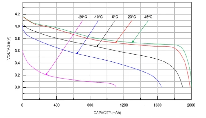
Discharge curves of Li-ion batteries at different temperatures
8. Number of lithium-ion battery cycles
In practice, whenever the accumulated discharge capacity is equal to the design capacity, it is recorded as a cycle.

Lithium-ion battery cycle life
The national standard stipulates the test conditions and requirements for the cycle life of lithium-ion batteries: charge at 1C for 150 minutes at 25 degrees room temperature, and discharge current at constant current 1C to 2.75V for a cycle. When one discharge time is less than 36 minutes, the test ends, and the number of cycles must be greater than 300 times.
-
This definition specifies that the cycle life test is carried out in a deep charge and deep discharge manner;
-
The cycle life must be more than 300 times after the execution of this mode, and the capacity is still more than 60%;
9, lithium-ion battery operating voltage range
-
Lithium cobaltate (LiCoO₂) battery:
-
Nominal voltage: about 3.6V
-
Charge cut-off voltage (full charge voltage) : usually 4.2V
-
Discharge cut-off voltage (minimum operating voltage) : usually 2.75V to 3.0V, in order to protect the battery, it is recommended not to terminate the discharge less than 3.0V in practical applications
-
-
Lithium nickel-cobalt manganate (NMC) battery:
-
Nominal voltage: Usually between 3.6V and 3.½V, depending on the proportion of NMC ternary materials (e.g. NMC111, NMC532, NMC811, etc.)
-
Charging cut-off voltage: generally 4.2V
-
Discharge cut-off voltage: similar to lithium cobalt acid battery, recommended not less than 3.0V termination discharge
-
-
Lithium nickel-cobalt aluminate (NCA) battery:
-
Nominal voltage: close to lithium cobaltate, about 3.6V
-
Charging cut-off voltage: Also 4.2V
-
Discharge cut-off voltage: similar to lithium cobaltate, not less than 3.0V is recommended to terminate discharge
-
-
Lithium iron phosphate (LFP) battery:
-
Nominal voltage: about 3.2V
-
Charge cut-off voltage: Usually set to 3.65V
-
Discharge cut-off voltage: More conservative, it is recommended to terminate discharge between 2.0V and 2.5V to ensure battery life and safety
-
-
Overall general scope:
-
Nominal voltage: Usually 3.7V (for most commercial lithium-ion batteries)
-
Normal operating voltage range: Generally 2.5V to 4.25V, covering the typical operating range of most lithium-ion battery types
-
Charge cut-off voltage: Typically 4.2V, which is the highest charge voltage for many lithium-ion battery designs
-
Discharge cut-off voltage: Between 2.0V and 3.0V is recommended depending on the type, depending on the battery chemistry and protection requirements
-
In practical applications, in order to protect the battery from damage, the battery pack is usually equipped with a battery management system (BMS), which monitors the voltage, current and temperature of each cell to ensure that the battery is operating within a safe range. BMS will stop the charging process when the battery charging reaches the preset cut-off voltage to prevent overcharging; Similarly, when the battery voltage drops to the preset minimum discharge voltage, the BMS will cut off the discharge loop to prevent overdischarge. These protections help extend battery life, prevent safety hazards such as thermal runaway, and maintain battery performance.
However, it should be noted that the above data is a typical value under normal circumstances, and the voltage range of the specific battery product should refer to the technical specifications and operating guidelines provided by its manufacturer.

Lithium ion battery voltage range
10, lithium battery protection board composition
The general lithium battery protection board is composed of a control IC, a MOS tube, a resistance capacitor, and a FUSE, as shown in the following figure.

Common lithium battery protection board circuit diagram
TH is temperature detection, and inside is a 10K NTC connected to the negative electrode of the battery; ID is the battery in place detection, generally 47K/10K resistance to the negative electrode, some 0R resistance; TH and ID are optional, and not all lithium batteries are available.
11, overcharge protection
When the battery is charged, the current (direction shown by the arrow) flows into the positive electrode of the battery pack and flows out of the negative electrode through FUSE. The two MOS tubes at the bottom are both on.

When the battery is charged, the current direction is shown by the arrow
When charging, the control IC X1 will always monitor the voltage between the 5th pin VDD and the 6th pin VSS. When this voltage is greater than or equal to the overcharge cut-off voltage and meets the delay time of the overcharge voltage, X1 will turn off the MOS tube Q2 by controlling the 3rd pin. After Q2 is turned off, the charging loop is cut off (Q2's body diode D2 is also reversed cut-off). At this point, the battery can only discharge.
Overcharge protection release conditions (meet one) :
1, the voltage at both ends of the cell drops to the overcharge recovery voltage of the protection IC.
2, add load discharge to the output end of the battery pack, discharge to the voltage is less than the overcharge protection voltage.
12. Over-discharge protection
When the load is discharged at both ends of the battery pack, the current (the direction shown by the arrow) is opposite to the charge, as shown in the figure below.
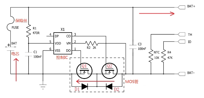
When the battery is discharging, the current direction is shown by the arrow
When discharging, the control IC X1 will also always monitor the voltage between the 5th pin VDD and the 6th pin VSS, when this voltage is less than or equal to the overdischarge cutoff voltage and reaches the delay time of the overdischarge voltage, the control IC X1 will turn off Q1 through the 1st pin, Q1 is turned off after the discharge loop is cut off (Q1's body diode D1 is reverse cutoff), this time, Batteries can only be recharged.
Overdischarge protection release condition: Remove the load, charge the battery pack, and when the voltage between VM-VDD reaches the overdischarge recovery voltage value, the control IC X1 will re-open the MOS tube Q1.
13, overcurrent protection/short circuit protection
Overcurrent protection refers to the protection of overdischarge current, the general control IC has two kinds of overcurrent protection and short circuit protection, the control IC always monitors the voltage value between VSS-VM, when the voltage value reaches the threshold of overcurrent protection or short circuit protection and meets the delay time, the control IC will turn off the MOS tube Q1 and cut off the discharge circuit.
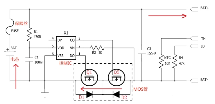
When the battery is discharging, the current direction is shown by the arrow
The condition of overcurrent protection is: remove the output load, and the control IC will automatically turn Q1 back on.
The voltage value of overcurrent protection is generally 0.1-0.2V, and the voltage value of short-circuit protection detection is generally 0.9V~2V, both of which are related to the control IC, and the two values are different for different ics.
The short-circuit protection voltage value refers to the on-voltage drop of the current flowing through Q1 and Q2, that is, it can be concluded that the greater the on-internal resistance of the MOS tube, the smaller the protection current value. For example, a MOS tube with an internal resistance of 20mΩ and a control IC with an overcurrent value of 0.15V is selected, the current for overcurrent protection should be: 0.15V/ (0.02*2) =3.75A.
14. FUSE protection after control IC failure
The FUSE protection mechanism after the failure of the control integrated circuit (IC) is an important fault protection method in circuit design to prevent system damage, safety hazards or uncontrollable conditions that may be caused by the failure of the control IC. By cutting off the faulty current or power supply, you can prevent overcurrent, overheat, and system disorder caused by IC faults, ensuring device safety and reducing potential losses. In actual design, FUSE and other protection measures should be reasonably configured based on specific application requirements and security standards to build a complete security protection system.


